John Szinger, 2001
Abstract
Foldinator is a software application for visualizing objects made by the sequential folding of flat sheet materials, and for generating annotated documents that record and display the sequence of steps in the object's creation, providing a useful set of instructions to others. Such sequences can be used to represent origami models, packaging items, displays, and many other products. In contrast to a generic 2D drawing or 3D CAD program, Foldinator models the special qualities of sheet material, particularly its geometric configuration with respect to the constraints of manipulating 2D materials in 3D space, and also its thickness, flexibility and other properties. Foldinator contains an object model for the sheet material and its geometric state, eliminating tedious redundancy on the part of the author trying to express such an object without the benefit of such a model, and allowing him or her to conduct simulations of the object under continual deformation.
Background
The goal of this project is to create Foldinator as a tool for intuitively exploring origami folding and documenting origami models in a sharable format. The initial version of the Foldinator will allow the sharing and display of documents over the World Wide Web, and will have a downloadable authoring tool for creating Foldinator origami models and documents. Future versions of the Foldinator will feature high-resolution graphic output suitable for print publication. I intend to make Foldinator publicly available as a shareware application to serve as a resource to the origami community and promote online sharing of origami models.
I am a software designer and developer, and a longtime paper folder. I see the Foldinator as an interesting development project and interface design problem. The idea of representing an origami simulation in an engaging, intuitive interface has a certain appeal, and the application of diagramming lends the effort some utility. I initially came up against the problem of origami diagramming several years ago, while preparing a set of model instructions for publication. My solution in 1994 was hand drawing, which seemed to be the best option given my resources at the time. However, it had a number of obvious drawbacks, not the least of which was the trouble of converting the diagrams into a format suitable for electronic distribution.
The Foldinator project arose as a response to this problem. I have been pursuing Foldinator since mid-year of 2000, at first mainly conceptually, by working out an approach to the application design. I have been developing the software since the fall of 2000.
Motivation
Making origami diagrams the old-fashioned way is hard. It requires specialized tools and skills, and is a complicated, tedious process, especially for complicated models. Since it involves a lot of repetition and minute variations, it seems like a good candidate for an automated, computerized approach.
Currently, someone wishing to use a computer to assist them in creating origami diagrams has several options to choose from among available software packages. One class of these is 2D drawing and illustration programs such as Illustrator, Freehand, CorelDraw, and their ilk. These programs, however, while removing some of the tedium by allowing the author to copy and paste, still have their drawbacks. The main shortcoming is the lack of a geometric or other kind of model for the paper and the operations performed. The author is required to manually construct all of this information in his representation, and at a level that simply emulates the appearance but not the underlying structure.
Another alternative is to use a 3D modeling and animation package such as AutoCAD, Mathematica, or 3D Studio Max. These tools, while allowing the author to create a model representing the origami, have drawbacks of their own. Firstly, these software packages tend to be expensive and complicated, requiring specialized skills to use and long experience to master. Also, the modeling systems they employ are generalized, not specific to paper and its properties, so many of the capabilities of the software are extraneous to the task at hand. Further, the 3D renderers used in these packages are not designed for origami models, although it would be possible to create appropriate render settings. To use a package like this for this task is probably overkill; one could spend a lot of time customizing the environment to be suited for this application, but there are many features one does not need that have to be dealt with.
My solution to this situation was to develop a custom application for modeling origami. Origami is a formal system and therefore well suited for software representation, and creating diagrams is a good application for an authoring tool or expert system. The geometry of paper obeys a relatively small set of well understood constraints. And similarly, the vocabulary of paperfolding includes a small set of operations, each of which can be represented in a computer simulation. The depth of the experience comes from the ability to repeat operations ad infinitum and to choose what operation to apply next every step of the way. Indeed, the same qualities that make origami an elegant, aesthetic and appealing art form in the real world are the ones that make it an interesting process to program as a computer simulation. Indeed, working on the development of Foldinator has deepened my understanding of origami, and caused me to rigorously formalize many of my intuitive notions about the properties, geometry, and behavior of folded paper.
Some Known Prior Work
When I began to consider developing the Foldinator, I searched for previous work done in the field. To my surprise, there was relatively little. Indeed, one of primary motivations for delivering this paper at 3OSME was to see if I could learn about other's work in this area.
Currently some origami books feature computer-generated diagrams, but many books still feature hand drawings. Sometimes these are very nuanced and beautiful; sometimes not. Additionally, origami diagrams are available on the World Wide Web, either downloadable, or viewable in the browser. These, however, tend to be simple static image or text/image formats such as html pages, .JPEG or .GIF images, or .PDFs. They vary greatly in quality and image resolution. And, as with their print counterparts, these documents have been laboriously hand-crafted.
John Montroll and Robert J. Lang seem to have some software expressly for modeling and diagramming origami. In their book Origami Sea Life (1990) I found this reference on page 256: "additional software used in the production of this book was written by Robert J. Lang". I spoke to Mr. Lang at 3SOME conference about this, and apparently he has been experimenting for a long time with various bits of software for origami diagramming, but to my knowledge has not published the software itself or any papers on it.
The only other prior art I was able to uncover was from the Wolfram Mathematica web site. Lucy Zamiatina has developed origami simulations in Mathematica. This project seems to have been devoted exclusively to modeling and did not address issues of diagramming or rendering.
Design Goals
In starting any software development project, is important to enumerate the design goals. The Foldinator has three primary design goals:
- Users can model an origami model on a computer,
- Users save out annotated steps to generate diagrams to share with others, and
- Users interact with an intuitive UI based on traditional origami symbols to manipulate the model.
Development Platform
I am developing Foldinator using a combination of Macromedia Director and Macromedia Flash. There are a number of reasons for this. Director, which is the main development environment, is very well suited for building interactive User Interfaces, and for rapid prototyping. It has high-level structures to represent and manage collections of visual and data objects, and includes an object-oriented programming language, Lingo, that is well suited for representing model and geometry. Additionally, Director has a powerful graphics management and display engine, which greatly simplifies the task of programming the visual display of the interface and of rendering the origami model.
Director also is advantageous in that it encapsulates Flash objects. Flash is designed for the flexible display and animation of resolution-independent vector-based graphic objects. Flash elements can be freely scaled, rotated, distorted and otherwise manipulated without loss of resolution and without introducing visual artifacts. Many of the UI objects in the Foldinator, and many of the 2D primitives that are used as components of the 3D model, are created in Flash and imported into Director.
Another important factor in my choice of development environment is that the resulting application will be available to the widest possible user base. The Foldinator authoring tool will be a downloadable application program available for both the PC and Macintosh platforms; Director makes cross-platform development very simple. The Foldinator document viewer will run inside any modern web browser as a Shockwave document. Foldinator origami model documents will be based on the .TXT format and accessible to both authors and viewers on any platform.
Object Representation
At the heart of the Foldinator application is an object called Paper. Paper begins its life in a new Foldinator document as an unfolded square of paper with two sides and (nominally) zero thickness. When the user creates a fold, the crease divides the square polygon into two smaller polygons joined with a common, hinged edge. As the model progresses in its development, new folds propagate thru multiple layers of paper, creating numerous new polygons in the model, according to the kind of fold. The details of this are managed automatically by the software.
Clarity of display for the origami model necessitates variation from "true" 3D projection. Rather, aligned layers of paper are shown systematically offset so that the viewer can read the diagram. This requires modification of the 3D engine to create the projection from the modeler to the renderer. See Figure 1 for an example of this projection applied to the Preliminary Fold.
Also, special attention was given to lines and line weights in the development of the model view. The language of origami diagramming requires subtle and meaningful distinctions between various kinds of lines, such as creases and edges, and the various kinds of dashed and dotted lines. In this regard the use of Flash has paid off handsomely.
The next higher level of object is the Scene. The Scene contains the Paper model, plus diagramming symbols such as arrows and dashed lines, as well as text annotations. The Scene is a composite 2D/3D object.
The Sequence contains a series of Scenes and represents the origami model as a work in progress or as the completed set of folding instructions. It also includes global annotations such as title, author, copyright information, and special instructions for folding the model that don't fall in a particular step.
A Sequence can be saved or loaded as a file. This is a Foldinator document. Currently the Sequence is encoded as a .TXT file. Rendered scenes are encoded as .BMP or .JPG files, and are referenced by the .TXT file. Support for .EPS or similar print-resolution images is planned for a future version of the Foldinator.
The User Interface
Now it's time for a guided tour of what the Foldinatorapplication will look like. There are three principal views of the origami model. These are: the Main View, the Map View and the Section View. Additionally, there is a Sequence View that provides a high level view of a series of diagram in thumbnail format. Within each view are various controls, tools, and other UI elements.
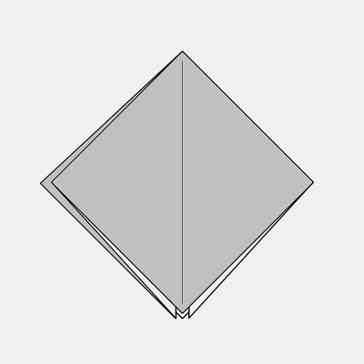
The Main View is, perhaps obviously, the main view where the author works on his origami creation. It is designed to look and act as much like as an origami model as possible. It is manipulable and annotatatable. See Figure 2 for an illustration of a model in the Main View.
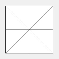
The Map View shows flat paper with all the folds in place. This is sometimes called the fold pattern. See Figure 3 for an illustration of a model in the Map View.
The Section View displays a cross-section thru model to show the arrangement of the various layers of paper. The line of the section can be set in the Main View. See Figure 4 for an illustration of a model in the Section View.

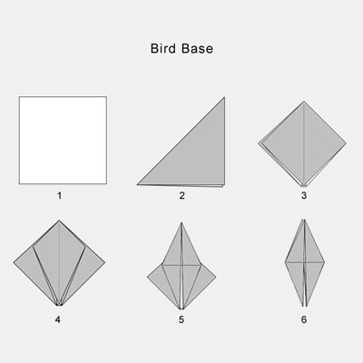
The Sequence View shows a series of thumbnails of the folding steps. The user may use this to step thru his model sequentially. See Figure 5 for an illustration of a model in the Sequence View.
Using Foldinator
Figure 6 shows the initial view of a new Foldinator document with the paper in the center of the screen and the various controls arrayed around it. This figure is taken from an early prototype version, so all of the controls are not fully fleshed out in detail. However, all of the main components are in place. At the top of the window is the Menu Bar, where the user can access various file- and application-level commands. On the left side is the Tool Palette, where the user can access the tools to work on the origami model. These tools use the icons of traditional origami notation, so their functions should be apparent to anyone familiar with reading origami diagrams. The use of some of the tools is detailed below. At the center bottom of the window is the Annotation Space, where the user can type in text instructions to accompany the symbolic markup of the step. Finally, at the lower right is located the Step Controls, which allow the user to execute the current step and move ahead to the next one, and also to move backward and forward thru the sequence of steps.
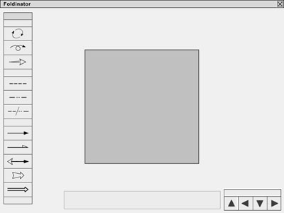
Usually the first thing a user will want to do when creating a model is set the Paper Properties. Access to this functionality is provided thru the Menu Bar or by right-clicking on the Paper itself. Paper properties include the shape or aspect ratio of the paper, as well as its color or graphic pattern, and its thickness. The default values for paper shape and color are: a square sheet with one white side and one side colored gray. As for other physical characteristics of the paper, currently "ideal" paper is the only representation supported. Ideal paper has zero thickness (although it cannot pass through itself or do other "impossible" things), absolute stiffness, always produces precise and permanent creases, and cannot be stretched, curved, cut or torn, only folded.
The top three tools on the Tool Palette are to Rotate, Flip, and Zoom the model. I implemented these functions first to test the basic integrity of the code that controls the 3D model and its projection into the rendering space, and the code that links user actions to the manipulation of the 3D model.
Making a Fold
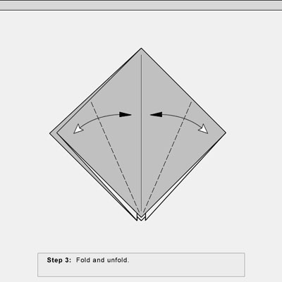
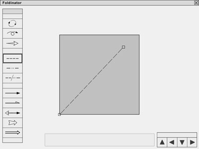
Figures 7 thru 10 illustrate the process of making a fold and executing a step in the Foldinator. To begin, the user selects the type of fold. Currently the available choices are Valley Fold, Mountain Fold, and Reverse fold. Support for more complex folds, such as Petal Fold, Squash, Rabbit Ear and Sink are planned, but most of these can be accomplished by sequences of simpler folds.
Figure 7 shows a Valley Fold selected and the user placing the fold by dragging a line. Foldinator supports Snap To by default, although it can be turned off. Most origami folds, especially at the beginning of the model, are placed relative to existing features of the geometry of the paper. The user can easily place a fold at the bisector of two existing lines, such as parallel or adjacent edges of the paper, or an edge and an existing crease, or two existing creases. The user can also snap to a point at the intersection of any pair of creases or the intersection of a crease and an edge, both for locating the end point of a crease or for locating the destination of a locatable point on a folded flap.
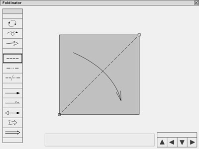
In Figure 8, the fold has been located, and now the direction of the arrow must be specified, that is, the user must indicate whether the lower right corner is to be folded up to the top left, or vice versa. When the second end point of the fold is placed, the arrow automatically appears, with the arrow head on whichever side of the line that the mouse happens to be. To change the direction of the arrow, the user simply drags the mouse across the line and clicks. The example illustrates an arrow of the type Fold, although the user can change the arrow to other types including Unfold and Fold and Unfold.
Once the fold is placed, the user may annotate the step, as shown in Figure 9. This is accomplished simply by clicking in the annotation field and typing. Sequential labels (e.g. "Step 1") are provided by default.

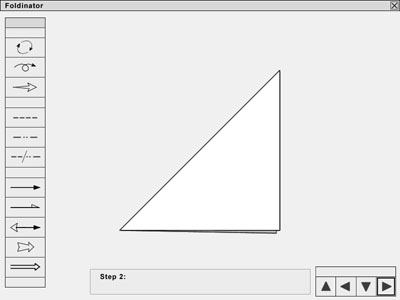
All that remains is to execute the step using the Step Controls in the lower right of the application. This is shown in Figure 10. When the user clicks on the "Next" icon, the model animates the action specified (in this case, a valley fold across the diagonal of the paper), and updates its internal state so as to be ready for the user to create the next step. Additionally, the Step Controls allow the user to pop up from the various Scene Views (Main, Map, and Section) to the Sequence view, to step down from the Sequence View into the Scene View, and to move backward or forward thru the various steps in the model sequence.
Foldinator also contains global document controls to allow the user to create new documents, open and save existing documents, and perform related functions. These are provided thru the Menu Bar.
Issues
A number of issues emerged as the development of the Foldinator proceeded. First among these is the look and feel of the application. I felt very strongly that the lines should appear smooth and free of aliasing artifacts, and spent a considerable amount of time arriving at a solution to this problem. Similarly, I put a lot of effort into developing a projection from the 3D model to the 2D image that would elucidate the features of the model that were important to its representation for folders. Choices for the development platform and the way in which I structured the code representation of the origami model emerged as a result of these priorities.
Some aspects of simulating an origami model appear to be difficult to implement, and I am deferring them until a future version of the Foldinator. I would very much like to support curvature in folds and in the paper itself. Many of the origami models I currently make that I would like to document feature a sculptural, curved approach in the finishing stages of the model. However, this will require me to introduce splines to the 3D model, which is currently based on polygons, and will require a reworking of significant amounts of code. Luckily, Macromedia has just released version 8.5 of Director, which includes mesh-based 3D geometry objects as part of an extensive new feature set to support 3D animation as an integral part of the Director environment, so I will be investigating converting my 3D engine to Director 8.5 in the near future.
Another potential issue has to do with the complexity of elaborate origami models in 3D. As it is still under development, I have not yet tested the Foldinator with very complex models as of yet. While I believe that the constraints I have implemented are sufficient to prevent the paper from folding thru itself or doing other "impossible" things, I have not proven in a rigorous mathematical sense that this is in fact the case. Also, I can envision a user folding a model so complex that at some point my projection produces an image which fails to achieve the visual clarity I am aiming for.
Finally, there is the issue of screen resolution vs. print resolution. Currently, all of the image projection and rendering functions are designed to display to the screen. While in principle, the Flash primitives that compose the images are resolution-independent, I have not yet implemented or tested the exporting the images at high resolution to a printable format.
Current Status and Future Goals
Foldinator is currently under development by Zing Man Productions. (Please note: the features described in this paper do not constitute a formal specification, and may change in the final release version.)
If public response to Foldinator 1.0 is sufficiently positive, I will continue to add features to create a more sophisticated version of the software. Planned features include: support for paper with non-zero thickness and other variable physical qualities, for paper of arbitrary non-rectangular shape, support for curved folds and curved paper, support for images to be mapped onto the paper as a texture map, and for print-quality rendering of the steps. I would also like to add support for multiple sheets of paper in a scene for creating geometrics and other compound origami models. Further, I am eventually planning on expanding the tool palette to support non-folding operations such as the ability to specify cuts, holes, tabs, slots, glue, staples and rivets to support generic sheet material fabrication.
Based on the initial feedback I have gathered from fellow origami enthusiasts, I expect that the Foldinator will fill a useful role in the community of paper folders who wish to share their creations with one another. I look forward to its completion and public release.
References
Origami for the Enthusiast, John Montroll, 1979 Dover Publications
Origami for the Connoisseur, Kasahara and Takahama, 1987 Japan Publications
Origami from Angelfish to Zen, Peter Engel, 1989, Dover Publications
Origami Sea Life, John Montroll and Robert J. Lang, 1990 Dover Publications